avr-rev (rev185)
My Arduino now has internet access! :D
Download: challenge.hex.gz
We are given a file challenge.hex, which is in the Intel HEX format. objcopy can be used to convert it to binary format.
objcopy --input-target=ihex --output-target=binary challenge.hex challenge.bin
The service reads in an input and gives an output that suggests it is parsing the input.
> 11111
11111
0

> aParse error, got this far:
a

> "a""a"
0

> [11"]"Parse error, got this far:
[11\"]\"
Emulation
To execute the program locally, an Arduino emulator is needed, and I used simavr which is really good. I cloned the repository and ran make in the root directory of it. I did this instead of apt install simavr because I also wanted to build the simduino binary under examples/board_simduino.
Apart from simduino, I also installed avr-gdb, avrdude, and picocom.
git clone https://github.com/buserror/simavr.git
cd simavr
make
sudo apt install -y gdb-avr avrdude picocom
With these installed, we can emulate and debug the program with a few terminals open
simduinoto start the emulated Arduino boardexport SIMAVR_UART_XTERM=1 cd simavr/examples/board_simduino obj-x86_64-linux-gnu/simduino.elf -d # -d to enable remote debugging # since remote debugging is enabled, make sure to connect avr-gdb # to the board and run continue first before doing anythingavrdudeto write the challenge program onto the Arduino boardavrdude -p m328p -c arduino -P /tmp/simavr-uart0 -U flash:w:challenge.hexpicocomto act as a serial monitor (the terminal of the Arduino board)picocom /tmp/simavr-uart0 # send ctrl-a ctrl-c so that we can see our own input that we typed in # which is disabled by defaultavr-gdbfor debugging (make sure to connect to the board and allow it to continue first so thatavrdudecan program it)avr-gdb -q challenge.hex target remote localhost:1234 c
And this is how it looks like altogether
Arduino and AVR Architecture
Arduino boards have an ATmega microcontroller chip, which runs an AVR processor core. AVR has a RISC architecture and is based on the Harvard architecture. What this means is the program and data memory lie in different memory units/spaces.
This is different from the von Neumann architecture which has the program and data lying in the same memory space, as seen on x86 machines. This is important to note because it affects the way AVR instructions work, which will be elaborated more later.
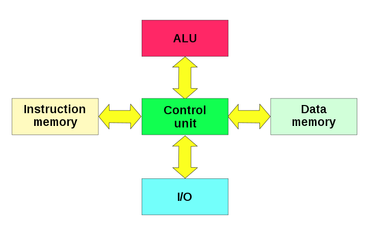
According to the Arduino documentation, there are three pools of memory in the microcontroller:
- Flash memory (program space), is where the Arduino program is stored.
- SRAM (static random access memory) is where the program creates and manipulates variables when it runs.
- EEPROM is memory space that programmers can use to store long-term information.
Flash memory and EEPROM memory are non-volatile (the information persists after the power is turned off). SRAM is volatile and will be lost when the power is cycled.
AVR instruction set
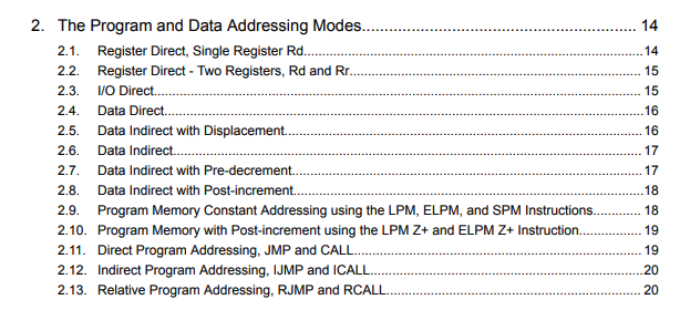
The best resource for the AVR instruction set is the AVR Instruction Set Manual itself. It contains everything we need to know, and everything is easily accessible through the table of contents.

The AVR processor has 32 registers (R0 to R31), and one unique thing about the AVR instruction set is it has 3 special registers X (R27:R26), Y (R29:R28) and Z (R31:R30).
Later, when opening the binary in Ghidra, we can also see a register W, I’m not sure where they got this name from, because I cannot find any information about it online. Anyways W is just the concatenation of registers R24:R23.
Program memory
First look at Z, which is normally used in loading program memory. Recall as mentioned earlier there are 2 separate memory spaces, the program space and data space. So, the instruction to load from program memory is completely different from the one to load from data memory.
The program memory is organized in 16-bit words, meaning each address in the program space points to a 16-bit value, unlike in x86 which only points to 8-bit values. But the Z register points to 8-bit values, so the address pointed needs to be twice of that in the program space. (I think this is easier to understand when looking at the program in a disassembler.)
For example, suppose program:030 contains the 16-bit value ABCDDBCACAFEBEEF. To load the value ABCDDBCA we need to set Z = 0x60 and for CAFEBEEF we need Z = 0x61.
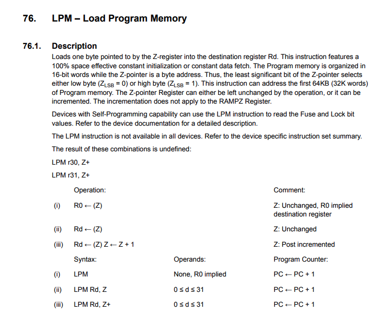
Only the Z register is used to load from program memory.
Data memory
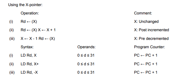
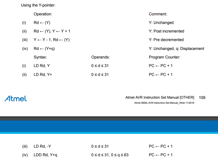
For loading from data memory, it is less troublesome. The address pointed by the X/Y/Z register directly maps to the address read from the data memory space, like what we would normally expect.
The following are snippets from the manual for the LD (Load Indirect from Data Space to Register) instruction.
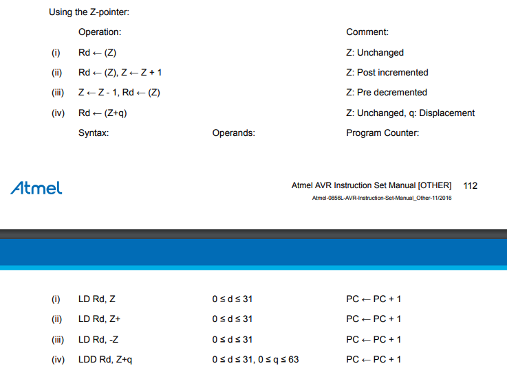
Data addressing modes
Like any other instruction set, there are a few types of addressing modes.
But the ones that I don’t think exist in x86 are the pre-decrement and post-increment modes. As the name suggests, the X/Y/Z register can be decremented before or incremented after loading from data memory.
For example ld R1, X+ loads the contents in the data memory pointed by X into R1, then increments X. Or, ld R1, -X decrements X, then loads the contents in the data memory pointed by X into R1.
This is used quite often so it is worth taking note of. The manual also describes each addressing mode very clearly.
Knowing these, the rest are pretty much the same as what we would see in other instruction sets such as x86 or ARM, consisting of arithmetic, branch, compare, and store/load operations.
ATmega microcontroller registers
The ATmega microcontroller is not just a CPU. It also has other things like I/O pins (to interact with the outside world), EEPROM (read only memory), etc. To interact with these devices, we need to read/write from/to a special set of status/control/data registers. Although they are called registers by name, they are actually not physical registers like R0-R31, but are located in the data memory space.
All information about these registers can be obtained from the ATmega datasheet. Here are some snippets taken from the Register Summary section of the ATmega datasheet that shows each register’s address in the data space.
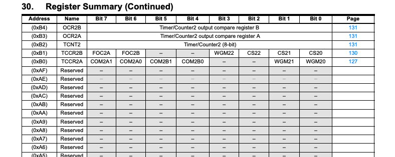
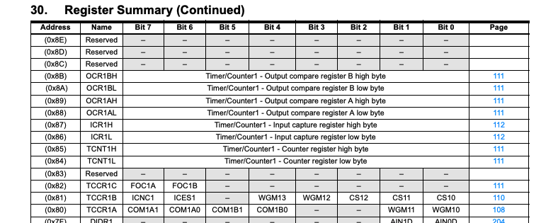
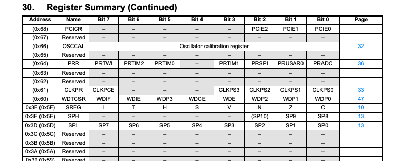
I will refer to these registers as the MCU registers, whereas the R0-R31 registers as the CPU registers to prevent confusion.
Analysis
Importing into Ghidra
To analyse the program, I opened the binary in Ghidra. There were a couple of options to choose from, but after trying them out, I found that the ATmega256 option works well, with all the MCU registers at the right location in memory. I believe the board used by the challenge service is an ATmega328p instead. There is no big difference between them from a reverse engineering perspective, just that the 256 one has more MCU registers that the 328p, which we can just ignore.
The start of the binary contains the IVT(interrupt vector table), which contains instructions when each interrupt is triggered. The RESET interupt, as its name suggests, is the one that will go to start of the program, like main in x86 binaries.
As mentioned earlier, the ATmega256 has a lot more MCU registers (hence more interrupts) than the ATmega328p, so the code for RESET overlaps with some of those non-existing entries in the IVT. So some manual work to clean up is needed.
Setup
Some things to take note before reverse engineering the program:
- Recall that for the
lpminstruction, the Z register is halved before dereferencing it in the program space. - In overall the decompiler is quite good at showing the control flow in pseudocode, but because often times two 8-bit registers are concatenated to form a 16-bit value, the resulting pseudocode for relevant operations will appear unnecessarily complicated, and it is way better to just look at the assembly code.
Here’s a simplified version of main, or better named setup.
- Copy the data from
code:835tomem:100 - Clear the data in
mem:156 - Set up USART for serial communication
- Enter the main process to interact with the user
void main(void)
{
  SREG = 0;
  memcpy(code:8c5, mem:100, 0x56);
  memset(mem:156, 0, 76);

  DAT_something = 0x56;
  setup_usart();
  DAT_something = 0x5b;

  process();
  do_nothing();

  return;
}
     code:0008c5 ff 08           dw         8FFh
     code:0008c6 a3 01           dw         1A3h
     code:0008c7 20 00           dw         20h
     code:0008c8 50 61 72        ds         "Parse fail"
                 73 65 20
                 66 61 69
   code:0008cd.1 54 65 73        ds         "Test"
                 74 00
     code:0008d0 5c 78 25        ds         "\\x%2.2x"
                 32 2e 32
                 78 00
     code:0008d4 25 75 00        ds         "%u"
   code:0008d5.1 2c 20 00        ds         ", "
     code:0008d7 3a 20 00        ds         ": "
   code:0008d8.1 7b 55 4e        ds         "{UNKNOWN}"
                 4b 4e 4f
                 57 4e 7d 00
   code:0008dd.1 0a 3e 20 00     ds         "\n> "
   code:0008df.1 0a 25 75        ds         "\n%u\n"
                 0a 00
     code:0008e2 50 61 72        ds         "Parse error, got this far:"
                 73 65 20
                 65 72 72
   code:0008ef.1 00              ??         00h
USART
USART stands for Universal Synchronous/Asynchronous Receiver/Transmitter, which is the protocol used by the Arduino to perform serial communication.
As we can see in the following code, the program reads and writes to UCSR0B, UCSR0C, and other MCU registers. USCR stands for USART Control and Status Register, hence it is used to control the USART operations on the Arduino. To understand the purpose of each write, we need to refer to the datasheet.
void setup_usart()
{
  write_volatile_1(UCSR0B, UCSR0B | 0b00011000);
  write_volatile_1(UCSR0C, 6);
  write_volatile_1(UBRR0H, R1);
  write_volatile_1(UBRR0L, 0b01000111);

  R23R22._0_1_ = 0x50;
  R23R22._1_1_ = 3;
  FUN_code_0004e1();

  R0 = read_volatile_1(SREG);
  watchdog_reset();
  write_volatile_1(WDTCSR,0x18);
  write_volatile_1(SREG, SREG);
  write_volatile_1(WDTCSR,8);
  Wlo = 0x18;
  Whi = 8;
  return;
}
For example, write_volatile_1(UCSR0B, UCSR0B | 0b00011000) turns on the 4th and 5th bit of UCSR0B, while write_volatile_1(UCSR0C, 6) sets UCSR0C to 0b110. According to the datasheet, this enables the receiver and transmitter of USART0, sets the mode to asynchronous USART, and the data mode to be 8N0 (8 bits data, no parity bit, 0 stop bit).
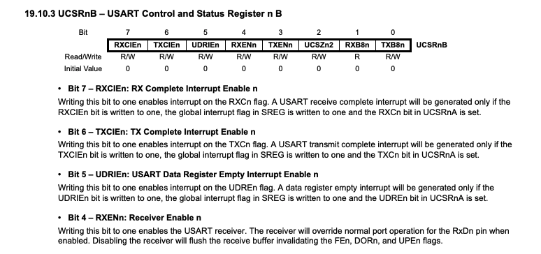
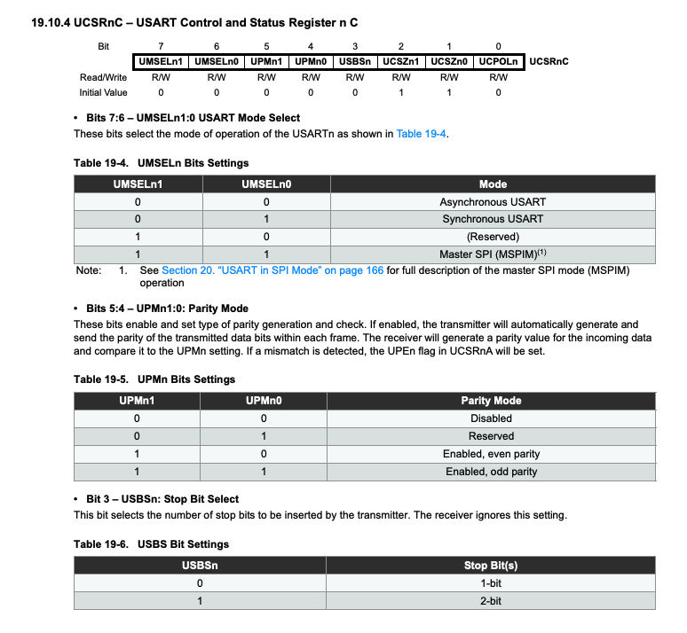
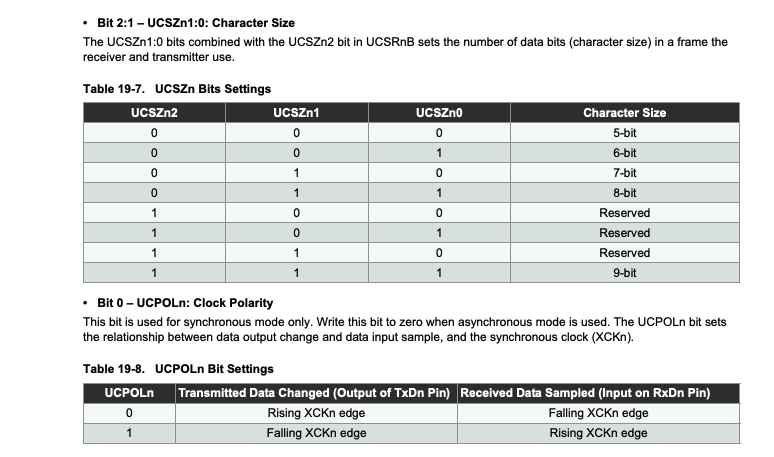
(There is an n in the datasheet because there can be more than 1 USART interface on the board.)
To summarize, this function
- Enables UART in 8N0 mode
- Does something that I didn’t reverse
- Sets up the watchdog timer (purpose is to restart the machine if it hangs for a certain duration)
Some failed attempts
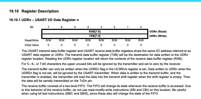
Cannot find UDRn
After USART is enabled, the program can either read from or write to the USART I/O Data Register (UDRn) to receive or send data through the serial port. The transmit and receive operations share this buffer, so in order for this to work properly, there is an underlying mechanism using some other registers or interrupts to let the program know when this register is available. Anyways not something to worry too much about here.
Since earlier UCSR0B was set to enable USART, I know that n=0, so I tried to search for references to UDR0, so that I can first identify the print and read functions in this program, just like what I would first do with any x86 program. But somehow I could not find any reference to any UDR at all, really not sure why.
Cannot find references to strings
At the start, the program copied some data from the program space to the data space, and this data contained some strings such as "> " or "Parse error, got this far:". I tried to search for references to the addresses that would contain these strings but also could not find any.
For both cases, I can’t tell if I got the addresses wrong or they were intentionally/unintentionally obfuscated.
User interaction
After this, the program enters a function that calls a series of functions to interact with the user through the serial port.
void process()
{
  something1();
  something2();
  something3();
  something4();
  something1();
  return;
}
Breakpoints on GDB
Hoping to get an idea of what each function does, I wanted to set a breakpoint after every one of them is called.
At this point, I have not tried setting breakpoints in GDB to inspect the program yet, but just clicking into functions to see if I can find anything interesting.
However, setting breakpoints for AVR in GDB doesn’t seem to be that straightforward. Suppose I want to break at address 0x321, I cannot just do break *0x321 as it will “help” me add an offset to the address, treating it as a pointer to the data space, but I want it to point to the program space. Still no idea what is the correct syntax to do this, but I found a workaround.
Somehow if I add an offset to the program counter ($pc), it works properly. So I just assigned $a to the $pc at the start, then offset it to the address I want. Also, I needed to multiply the offset by 2 because memory in the program space is 16 bits wide.
set $a=$pc
break *($a-0x6aa+0x321*2)      # suppose $pc=0x6aa, this sets a breakpoint at 0x321
Quickly, I was able to name the functions.
void process()
{
  print_output();
  read_input();
  echo_input();
  get_output();
  print_output();
  return;
}
Reading/parsing input
I decided to look more into read_input, since that is the most important part, to know what I need to enter. With more inspection, I found a function that looks like it is parsing the input.
void read_input()
{
  W = parse();
  switch (W)
  {
    case 1:
      // do something
      ...
      break;
    case 2:
      // do something
      ...
      break;
    case 3:
      // do something
      ...
      break;
    case 4:
      // do something
      ...
      break;
  }
  ...
}
void parse()
{
  do {
    W = read_char();
  } while(W == ' ' || W == '\t' || W == '\n' || W == '\r')

  if (W == '"') {
    // continue reading until reach the next " character
    ...
    W = 2;
    return;
  }
  else if (W == '{') {
    W = 3;
    return;
  }
  else if (W == '}') {
    W = 4;
    return;
  }
  else if (W == ':') {
    W = 5;
    return;
  }
  else if (W == '[') {
    W = 6;
    return;
  }
  else if (W == ']') {
    W = 7;
    return;
  }
  else if (W == ',') {
    W = 8;
    return;
  }
  else {
    // keep reading as long as input character is still a digit
    // and save the number in [R1:R0]
    W = 1;
    return;
  }
}
It seems that in parse, different inputs result in different numbers returned, which is exactly what a parser does. The characters also look familiar as they can be used to form different types of values (number, string, dictionary, list) in most programming languages. Therefore, the type for each number can be summarized as follows.
1:    number
2:    string
3,4:  dict
6,7:  list
5:    ':'
8:    ','
With this knowledge, read_input can be rewritten as the following.
void read_input()
{
  W = parse();
  switch (W)
  {
    case NUMBER:
      // store some values to some data structure
      ...
      break;
    case STRING:
      // store some values to some data structure
      // and memcpy string to some buffer
      ...
      break;
    case DICT:
      W = read_dict_contents();   // recursively calls read_input inside this function
      break;
    case LIST:
      W = read_list_contents();   // recursively calls read_input inside this function
      ...
      break;
  }
  ...
}
Clearly, to store such type of values, there must be a certain data structure used by the program. I decided to skip this first and proceed to look at get_output, as there must be something related to the flag in there.
Flag is stored in EEPROM
Inside get_output there are a bunch of things going on, that I could not understand because I have not reversed the data structure yet. However, I saw a function that seems to be reading data from the EEPROM. Well, I’m guessing it must have something to do with the flag.
void get_output()
{
  if (W == 3) {
    ... // load W from data structure
    if (W == 1)
      if (W == 1337) {
        ... // load W from data structure
        if (W == 2) {
          ... // load some stuff from data structure
          do {
            ... // load some stuff from data structure
            read_eeprom();
            ... // something's going on
          } while(<something is compared>)
        }
      }
    }
  }
  ... // i guess whatever's down here doesn't really matter anymore
}
The read_eeprom function is quite straightforward. It polls until the EEPROM device is ready, writes the address to be read from into EEAR (EEPROM Address Register), then reads from EEDR (EEPROM Data Register).
void read_eeprom(undefined2 param_1)
{
  while ((read_volatile_1(EECR) & 2) != 0);
  write_volatile_1(EEARH, W_high_byte);
  write_volatile_1(EEARL, W_low_byte);
  write_volatile_1(EECR, read_volatile_1(EECR) | 1);
  W = read_volatile_1(EEDR);
}
Get Flag
Looking at the checks done in get_output, I just guessed that the numbers could be the type of value that is sent as input. This can be easily verified by setting breakpoints after the comparisons, and I found out that the input must be in the form {1337: "something here"}, in order to reach the code that reads from the EEPROM.
With the input above, I was able to get the program to print an output that seems to change based on the string I provided. Upon more testing, I realized it compares my string with the data in the EEPROM character by character, until there is a mismatch, then it prints the value difference between my wrong character and the correct character.
A simple script can be used to get the data stored in the EEPROM.
from pwn import *

def aaa(s):
    return chr((ord('}')-s)%256)

flag = '{1337: "}'
r = remote("avr-01.play.midnightsunctf.se", 1337)
while(True):
    r.sendlineafter("> ", flag+'}"}')
    r.recvuntil(flag + '}"}')
    r.recvuntil("\r\n")
    d = int(r.recvuntil("\r\n").strip())
    flag += aaa(d)
    print(flag)
By the time I solved this I had 5 minutes left :p, so I didn’t try the subsequent challenges avr-pwn and avr-own. But knowledge of the data structure used by the program was definitely necessary to solve those parts. There’s a writeup by hgarrereyn who solved all three parts of the challenge 👏🏻👏🏻.
Some link dumps to videos by LiveOverflow: